
Joint width is the single most controllable variable in sealant joint design. Get it right and the sealant accommodates building movement without stress concentration, adhesion loss, or fatigue cracking. Get it wrong and no product chemistry will save you.
The core relationship is straightforward: required joint width = total expected movement ÷ sealant movement capability (expressed as a decimal). A sealant rated ±25% movement capability installed in a 12 mm joint can handle ±3 mm of movement. If your building actually moves ±6 mm, you need a 24 mm joint or a sealant rated ±50%. That calculation, from ASTM C1472, is where every joint design starts.
Three quick rules before you read further:
- Do: Size the joint to actual calculated movement, not to the sealant’s maximum rated capability.
- Do: Maintain a 2:1 width-to-depth ratio up to 25 mm, with a minimum bead size of approximately 6 mm.
- Don’t: Assume wider is safer. Oversized beads sag, accumulate more strain energy, and can fail faster than correctly sized narrower joints.
Table of Contents
- How to size a sealant joint: formulas, worked examples, and a width-to-depth table
- Selecting a sealant matched to your joint width and expected movement
- Why installation timing, backer rod, and workmanship often matter more than width alone
- What lab tests and field studies tell us about freeze–thaw and joint width
- Practical field advice for Canadian projects
- Key takeaways
- The part most specs get wrong
- Kettlecontracting’s caulking and joint sealing services for GTA projects
- Key standards, technical papers, and practical references
- FAQ
How to size a sealant joint: formulas, worked examples, and a width-to-depth table
Worked example A: aluminium window perimeter joint
- Aluminium mullion length: 3 m
- α for aluminium: 23 × 10⁻⁶ /°C
- Ontario design temperature range (winter low to summer high): approximately 65°C (−30°C to +35°C)
- ΔL = 23 × 10⁻⁶ × 3,000 mm × 65 = a few millimeters within typical thermal expansion expected for aluminium components in Ontario
- Sealant movement capability: ±25% (MC = 0.25)
- Required width: thermal expansion divided by movement capability yields a moderate joint width appropriate for aluminium mullions
- Add construction tolerance allowance to ensure a safety margin over calculated width
Worked example B: concrete panel free joint
- Panel length: 6 m
- α for concrete: 10 × 10⁻⁶ /°C
- ΔT: 65°C
- Thermal ΔL = 10 × 10⁻⁶ × 6,000 × 65 = a few millimeters consistent with concrete thermal movement in Ontario
- Include an allowance for drying shrinkage when sealing new concrete joints
- Total expected movement includes thermal plus shrinkage allowances
- Sealant movement capability: ±25% (MC = 0.25)
- Required width is the total expected movement divided by the sealant movement capability, resulting in a joint width in the low tens of millimeters range
The Sikaflex joint design guide offers a quick conservative field check for concrete panels: Bmin = L × 3.5 mm/m. For a 6 m panel that gives 21 mm, which aligns with the thermal calculation above before shrinkage is added.
Width-to-depth guidance
| Joint width (mm) | Target depth (mm) | Width:depth ratio | Notes |
|---|---|---|---|
| 6–12 | 3–6 | 2:1 | Minimum practical bead; use closed-cell backer rod |
| 13–19 | 6–10 | 2:1 | Standard range; hourglass profile achievable |
| 20–25 | 10–13 | 2:1 | Approach upper limit; verify non-sag if vertical |
| Over 25 | 12–15 | ~2:1 | Non-sag formulation required; consider two-stage fill |
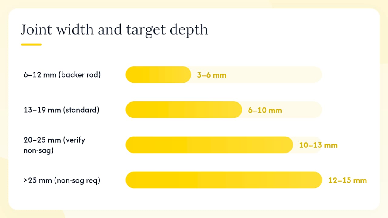
For joints wider than 25 mm, the 2:1 ratio still applies but a non-sag or gun-grade formulation rated for that geometry is mandatory. Depth beyond 13 mm adds cost and material without improving performance.
Selecting a sealant matched to your joint width and expected movement
Movement capability classes
ASTM C920 classifies sealants by movement capability tested under ASTM C719: ±12.5%, ±25%, ±35%, and ±50% of the original joint width. ISO 11600 uses a parallel classification system. What these percentages mean in practice: a ±25% sealant in a 20 mm joint can handle ±5 mm of movement. If your calculated movement is ±7 mm, you either widen the joint to 28 mm or upgrade to a ±35% product.
ICRI guidance is direct on this point: if movement exceeds a sealant’s rated capability, failure is likely. Matching the movement rating to actual calculated movement is not optional.
Procurement checklist
Before approving a sealant submittal, verify:
- Movement capability class per ASTM C719 (confirm it covers your calculated ΔL at the specified width).
- Sag/non-sag designation (non-sag required for vertical joints over ~12 mm wide).
- Service temperature range (must cover Ontario’s −30°C to +35°C minimum).
- Primer requirements for your specific substrates.
- Maximum recommended depth per the manufacturer’s datasheet.
- Compatibility with backer rod material (closed-cell polyethylene is standard).
Specify sealants using ASTM C920 Type S or M, Grade NS or P, Class 25 or 50, Use NT/G/A/O as applicable. Reference ASTM C1472 in the spec for joint width calculation methodology, and include Sika joint sealing guidance as a design reference where appropriate. MasterSpec sections 07 92 00 and SPECTEXT 07920 both provide model language for these requirements.
Why installation timing, backer rod, and workmanship often matter more than width alone
Backer rod: the most under-specified component
Backer rod controls sealant depth, prevents three-sided adhesion, and creates the hourglass cross-section that distributes stress away from the bondline. Use closed-cell polyethylene foam rod sized at 25% larger in diameter than the joint width so it compresses slightly and seats firmly. Open-cell rod absorbs moisture and can cause outgassing blisters in the sealant. Bond-breaker tape is the alternative for joints too shallow for rod.

Three-sided adhesion, where the sealant bonds to both faces and the back of the joint, eliminates the hourglass geometry and creates a rigid bead that tears under movement. The USDA Forest Products Laboratory identifies this as one of the most common installation errors in the field.
Pro Tip: Size your backer rod at 1.25× the joint width. A 20 mm joint gets a 25 mm rod. This gives you the compression fit needed to hold depth without the rod sinking or shifting before the sealant is tooled.
Installation timing and seasonal extremes
Joints installed at their narrowest seasonal dimension (typically mid-winter in Ontario) will be in tension for most of the year. Joints installed at their widest (peak summer) will be chronically in compression. Neither condition is catastrophic if the joint was sized correctly, but installing without a seasonal allowance built into the design width removes the safety margin entirely.
For Canadian projects, the practical rule is to install when the joint is at or near its mid-range dimension, typically in spring or fall. If installation must happen in winter, the design width needs an explicit cold-weather allowance. Guidance on seasonal installation timing is worth reviewing before scheduling exterior work.
Installation checklist for site supervisors
- Confirm substrate is dry, clean, and free of dust, oil, and old sealant residue.
- Verify joint width at multiple points along the joint; flag locations outside tolerance.
- Install backer rod to correct depth before applying sealant.
- Apply primer to both substrate faces where required by the datasheet; allow full cure time.
- Apply sealant in a single continuous pass; avoid starts and stops mid-joint.
- Tool immediately to a concave profile using a dry, clean tool; concave tooling compresses the sealant against the substrate and reduces bondline stress.
- Remove masking tape before the sealant skins.
- Record ambient temperature, substrate temperature, and relative humidity at time of application.
| Step | Common error | Consequence |
|---|---|---|
| Substrate prep | Moisture or contamination left on surface | Adhesion failure within first season |
| Backer rod | Rod too small; sealant bonds to back wall | Three-sided adhesion, tearing under movement |
| Sealant depth | Bead too deep relative to width | Rigid cross-section, bondline stress concentration |
| Tooling | Convex or flat profile | Reduced substrate contact, stress at centre |
| Timing | Applied at seasonal extreme | Biased tension or compression from day one |
Surface contamination and adhesion failure are the dominant causes of early joint failure. ASTM C794 adhesion-in-peel testing on representative substrate samples before committing to a sealant type is the most effective single step a project team can take to reduce risk.
What lab tests and field studies tell us about freeze–thaw and joint width
ASCE 1995 freeze–thaw study
The ASCE 1995 study on joint width and freeze–thaw effects produced a finding that surprises most specifiers: in controlled freeze–thaw cycling, a 6.5 mm joint showed higher failure resistance than a 19 mm joint under certain test conditions. The mechanism is that a smaller bead volume means less material subject to thermal cycling stress, and the geometry can produce lower absolute deformation for the same temperature swing. The takeaway is not to specify undersized joints, but to understand that wider is not automatically more durable. Correct sizing for actual movement, not maximum possible width, is what the data supports.
Virginia Tech performance evaluation
The Virginia Tech performance-based evaluation concluded that matching sealant movement capability to actual horizontal joint movement is the critical determinant of field performance. Joint width alone does not predict success. A correctly sized joint with a properly matched sealant outperforms an oversized joint with a mismatched product in every test condition the study examined.
Dynamic movement and accelerated weathering
Laboratory accelerated exposure testing confirms that dynamic movement combined with outdoor weathering degrades sealants faster than either condition alone. The implication for Canadian projects is direct: joints that experience large seasonal movement amplitudes, as they do in Ontario’s climate, need conservative sizing and high-movement-class sealants, not just UV-stable chemistry.
Preconstruction testing recommendation: Before finalising joint geometry and sealant selection on any project with significant movement, run ASTM C794 adhesion-in-peel tests on actual project substrates, conduct a mock-up joint at the specified width and depth, and cycle it through at least one temperature extreme before accepting the assembly. This step catches adhesion incompatibilities and geometry errors before they are replicated across hundreds of metres of joint.
- Request adhesion test results on project-specific substrates, not just generic datasheet values.
- Include a mock-up acceptance criterion in the specification: minimum peel strength and no adhesion failure after cycling.
- Specify that mock-ups be installed at the same time of year and temperature conditions as the main work.
- Review caulking lifespan in commercial building systems for context on how freeze–thaw cycles affect long-term durability.
Practical field advice for Canadian projects
Ontario’s climate puts sealant joints through roughly 65°C of annual temperature range, with freeze–thaw cycling concentrated in the shoulder seasons. That is not a forgiving environment for undersized or poorly installed joints. Here is what to watch for on GTA and broader Ontario projects.
-
Check substrate age on concrete. New concrete continues to shrink for months after placement. Installing sealant in joints adjacent to concrete less than 28 days old means the joint will narrow further after installation, adding compression to the bead. Allow full cure and, where possible, include a drying shrinkage allowance in the design width.
-
Measure actual joint widths before ordering sealant. Formwork tolerances on concrete panels routinely produce joints 3–5 mm narrower or wider than the drawing dimension. A joint specified at 20 mm that is actually 15 mm on site has a completely different movement capacity. Measure first, then confirm the sealant movement class is still adequate.
-
Flag oversized beads on vertical joints immediately. A bead wider than 25 mm on a vertical surface with a standard gun-grade sealant will sag before it cures. Non-sag formulations are not optional above this width; they are the only way to maintain the geometry needed for correct stress distribution. Common construction defect examples include sagged vertical beads that look acceptable on the day of installation but fail within one freeze–thaw season.
-
Schedule exterior caulking for spring or fall. Mid-summer installation on south-facing joints means the substrate is near its maximum expansion; the joint is at its narrowest. Mid-winter installation on north-facing joints means the substrate is near its maximum contraction; the joint is at its widest. Both extremes reduce the effective movement allowance. Spring and fall installation, when joints are near mid-range, gives the sealant the best starting geometry.
-
Set maintenance inspection intervals for high-movement joints. Expansion joints on commercial buildings in Ontario should be inspected every 3–5 years at minimum. Window perimeter joints on high-rise buildings, where differential movement between the glazing system and the structure is significant, warrant inspection every 2–3 years. Look for surface cracking, adhesion loss at the bondline, and compression bulging. Catching these early avoids water infiltration and the far greater cost of substrate repair. Proper exterior sealant maintenance extends building envelope life considerably.
-
Document mock-up locations and results. On commercial projects, mock-up joints should be installed in a location that will remain accessible for inspection throughout the project. Record the joint width, depth, sealant batch number, ambient conditions, and primer used. This documentation is the first thing a forensic investigation asks for when a joint fails.
-
Use the best window caulk suited to Canadian winters. For window perimeter joints specifically, silicone or high-movement hybrid sealants rated for service down to −40°C are the practical choice. Guidance on window caulk for Canadian winters covers product selection in more detail.
Key takeaways
Joint width sets the strain your sealant must carry on every movement cycle, and getting that calculation right before installation is the difference between a joint that lasts decades and one that fails in its first Ontario winter.
| Point | Details |
|---|---|
| Minimum bead size and ratio | Maintain a 2:1 width-to-depth ratio with a minimum bead width of approximately 6 mm. |
| Calculate before you specify | Use W = ΔL ÷ MC; add a safety factor for construction tolerances and installation season. |
| Match movement class to actual movement | A ±25% sealant in a 20 mm joint handles ±5 mm; if your joint moves more, widen it or upgrade the sealant class. |
| Workmanship drives outcomes | Backer rod, surface prep, and tooling determine whether the correct geometry is actually achieved on site. |
| Kettlecontracting’s approach | Kettlecontracting sizes joints to calculated movement, specifies backer rod and mock-up testing, and schedules installation for Ontario’s mid-range seasonal conditions. |
The part most specs get wrong
Most joint failures on Canadian buildings are not chemistry failures. They are geometry failures, and most of those trace back to one of two decisions: the joint was sized to the sealant’s movement capability rather than to the building’s actual movement, or the backer rod was skipped or undersized and the bead bonded to three sides.
The ASCE freeze–thaw data makes a point worth sitting with: a smaller, correctly sized bead can outperform a larger one. That runs against the instinct to go wider for safety. The real safety margin comes from accurate movement calculation, a matched movement class, and a correctly formed hourglass cross-section, not from adding millimetres to the joint width.
For specifiers, the practical implication is to run the ASTM C1472 calculation on every joint type in the project, not just the ones that look challenging. Window perimeter joints on aluminium systems in Ontario move more than most architects expect, and the thermal calculation usually produces a required width that is larger than the standard 12 mm detail that gets copied from project to project.
For contractors, the implication is simpler: measure the actual joint before you load the gun, use the right backer rod, and tool to a concave profile every time. Those three steps fix more joint failures than any product upgrade.
Kettlecontracting’s caulking and joint sealing services for GTA projects
Kettlecontracting works with architects, engineers, property managers, and general contractors across the Greater Toronto Area on exactly the kind of joint design and installation challenges this article covers. The concrete difference: every commercial project starts with a preconstruction review of joint widths against calculated movement, substrate-specific adhesion testing, and a mock-up before full installation begins.

Services directly relevant to joint width and sealant performance include joint design consultation, specification review against ASTM C920 and C1472 requirements, preconstruction mock-ups and ASTM C794 adhesion testing, high-performance installation of silicone, polyurethane, and hybrid sealants, and scheduled maintenance programmes for high-movement commercial joints. Climate-aware scheduling is standard practice, not an add-on.
For property managers concerned about energy efficiency and airtightness, correctly sized and installed sealant joints are one of the highest-return envelope improvements available. For specifiers who want to understand the full range of joint types before finalising a design, the exterior joint sealing guide covers system-level choices in detail.
To discuss joint sizing, specification review, or a preconstruction testing programme for your project, visit the Kettlecontracting services page or reach out directly.
Key standards, technical papers, and practical references
Use these sources when writing specifications, reviewing submittals, or setting up QA protocols.
- ASTM C920 — Standard specification for elastomeric joint sealants; defines Type, Grade, Class, and Use designations. Include in every sealant specification section.
- ASTM C719 — Test method for adhesion and cohesion of elastomeric joint sealants under cyclic movement; the basis for movement capability class ratings.
- ASTM C1472 — Standard guide for calculating movement and other effects when establishing sealant joint width; the primary calculation reference for specifiers.
- ASCE 1995 freeze–thaw study — Empirical data on how joint width interacts with freeze–thaw cycling; supports the argument that correct sizing outperforms maximum width.
- Virginia Tech performance evaluation (Khuri, 1998) — Performance-based assessment of joint sealants for concrete; useful for movement capability matching and preconstruction testing protocols.
- USDA Forest Products Laboratory TechLine — Practical guidance on width:depth ratios, backer rod, hourglass cross-section, and minimum bead sizes; good reference for site supervisors.
- Sika joint sealing technology guide — Manufacturer-agnostic overview of movement capability, non-sag requirements, and joint geometry; useful for material selection sections of specs.
- Sikaflex joint design and calculation guide — Worked examples and the Bmin = L × 3.5 mm/m field rule for concrete panels; practical for design calculations.
- ICRI concrete repair sealant guidance — Movement rating calculations and adhesion testing for concrete repair joints; supports specification of movement class and field testing requirements.
- Conspectus/MasterSpec exterior sealant joint tips — Specification-level checklists including drying shrinkage allowances, construction tolerances, and installation season guidance; model language for MasterSpec section 07 92 00.
- ICCONDA/CIB dynamic movement and degradation report — Laboratory evidence that movement amplitude accelerates weathering; supports conservative sizing and preconstruction dynamic testing.
FAQ
What is the recommended minimum width for a sealant joint?
The minimum practical bead width is approximately 6 mm, with a 2:1 width-to-depth ratio. Below 6 mm, the bead is too thin to accommodate construction tolerances or meaningful movement without overstressing the adhesion interface.
What is the correct width-to-depth ratio for sealant joints?
The standard ratio is 2:1 (width to depth) for joints up to 25 mm wide. This geometry produces the hourglass cross-section that distributes movement stress through the bead body rather than concentrating it at the bondline.
What are the most common sealant installation mistakes?
The three most frequent errors are skipping or undersizing the backer rod (causing three-sided adhesion), installing sealant on contaminated or wet substrates, and sizing the joint to the sealant’s maximum rated capability rather than to the building’s actual calculated movement. ASTM C1472 identifies poor workmanship and incorrect joint sizing as the leading causes of joint non-performance.
What is the most important factor in sealant retention?
Adhesion to the substrate is the primary retention factor, and it depends on surface preparation, correct primer selection, and substrate moisture content at the time of application. Movement capability matching is the second critical factor: a sealant that is repeatedly cycled beyond its rated movement class will fail regardless of how well it adheres initially.
How do I calculate the required joint width for a Canadian building?
Use W = ΔL ÷ MC, where ΔL is total expected movement (thermal plus shrinkage) and MC is the sealant’s movement capability as a decimal. For Ontario’s roughly 65°C annual temperature range, thermal movement on a 3 m aluminium member is a few millimeters. Divide by 0.25 for a ±25% sealant to get a minimum width appropriate for aluminium mullions, then add a construction tolerance allowance per ASTM C1472.